Proximity Switch from Stord

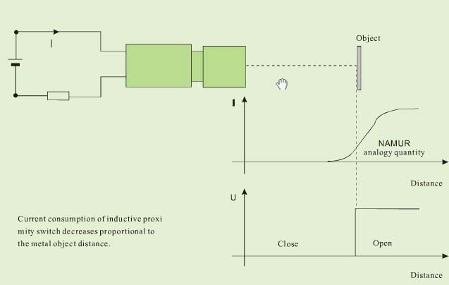
Working principle of inductive proximity switch

Inductive proximity switch is composed of three parts: oscillator, switch circuit and magnified output circuit. The oscillator will generate an alternating electric field. When the metal object approaches this electric field and reaches the induction distance, whirlpool will generate in metal object, resulting in attenuation of vibration and then stop. The change of vibration and stop of oscillator is treated by behind stage magnified circuit and converted to switching sign, triggering driving control for non-contact detection.
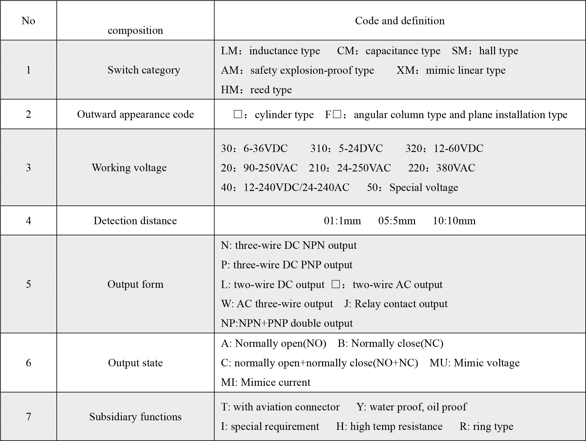
 Model explanation of proximity switch

Main features:
- compact volume;
- high precision of repeated location;
- diversified exterior;
- good performance of anti-interference;
- many output forms;
- high on-off frequency;
- wide voltage range;
- dust proof, vibration proof, water proof and oil proof;
- with short-circuit protection and inverted connecting protection;
- long service life.
Application illustration of proximity switch
-
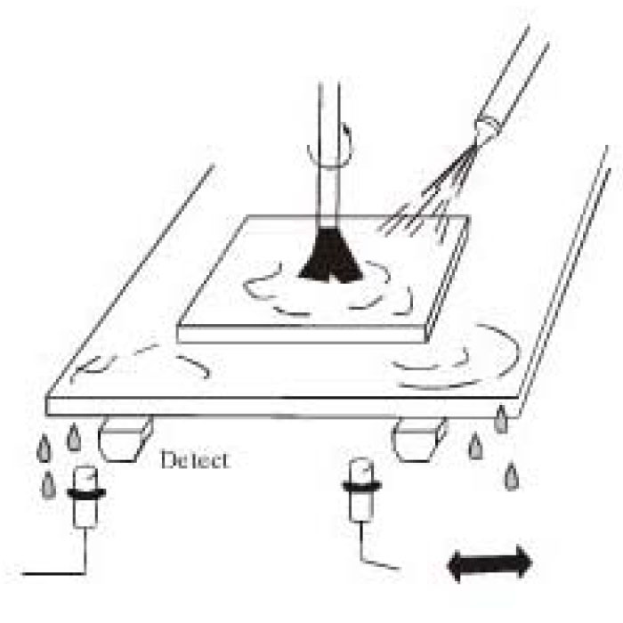
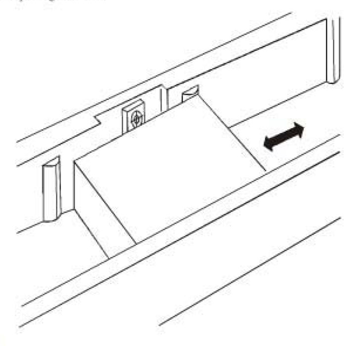
- Stopper detection of grinding machine
-
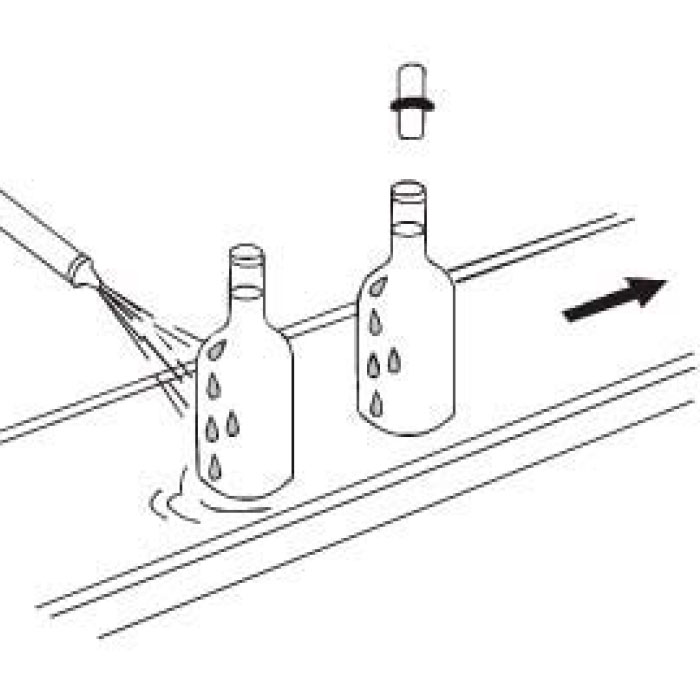
- Bottle lid detection
-
- Spacing detection
-
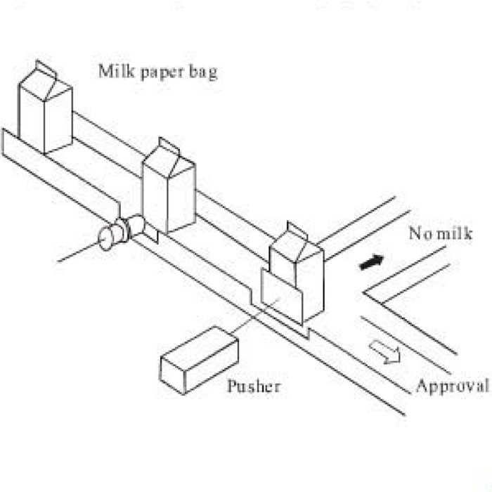
- Inspection of the existing of milk inside the paper package
-
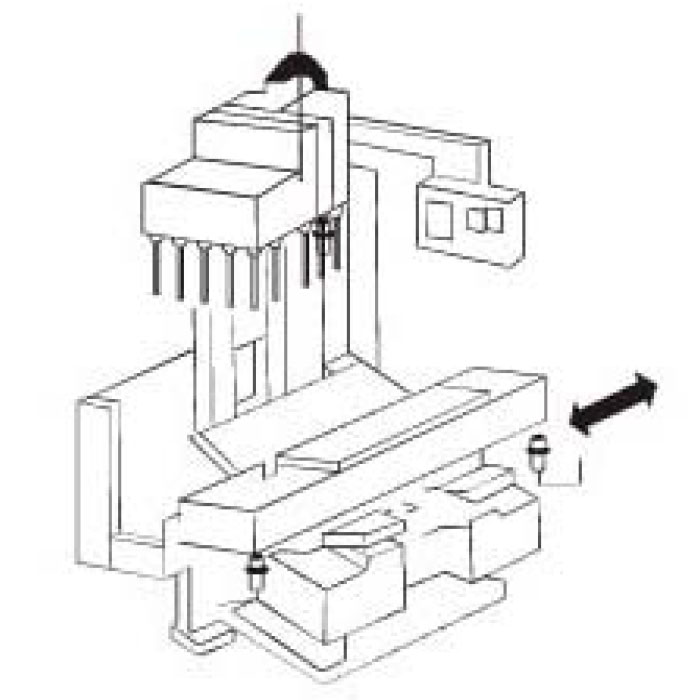
- Various location detection of machinery process center
-
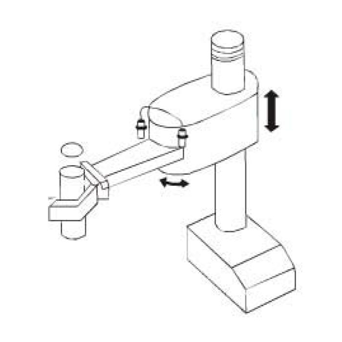
- Arm location detection of robot
Features of proximity switch
Main features
Take high frequency oscillation type proximity sensor (front detector) as representative example to briefly explain general features of proximity switch.
Explanation of technical terms
-
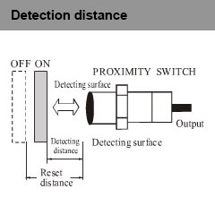
- Move the detected object according to assigned method, the distance from the reference position (reference plane) to the detecting action (resetting).
-
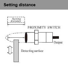
- Including the effects like temperature and voltage, without error action the distance passed through from the practical detection surface to the objected object.
-

- Take as standard detected object to detect the basic performance. The shape, size and material have been determined.
-
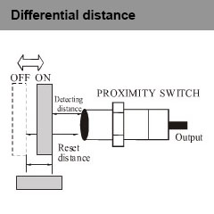
- The absolute value of the distance difference between the distance to action and the distance to resetting.
-
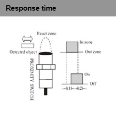
- T1: when the objected object enters the action zone, the time from proximity sensor being in action state to output appearance. T2: the time from leaving action zone to output disappearance.
-
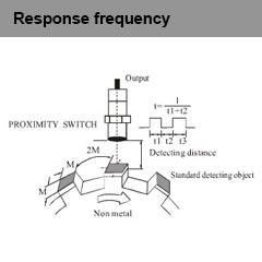
- Work out the tracking output times per second by repeatedly approaching the detected object. Brief detection method sees the above diagram.
Series connection and parallel connection
-
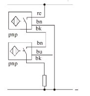
- Series connection of three-wire DC and three-wire DC sensor
-

- Parallel connection of three-wire DC and three-wire DC sensor
-
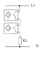
- Series connection of two-wire AC sensor
-
- Parallel connection of two-wire AC sensor
-
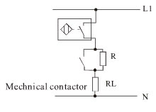
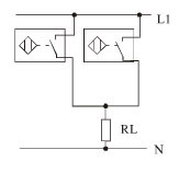
- Series connection of machinery switch and AC sensor
-

- Parallel connection of machinery switch and AC sensor
Correct use, installation and cautions
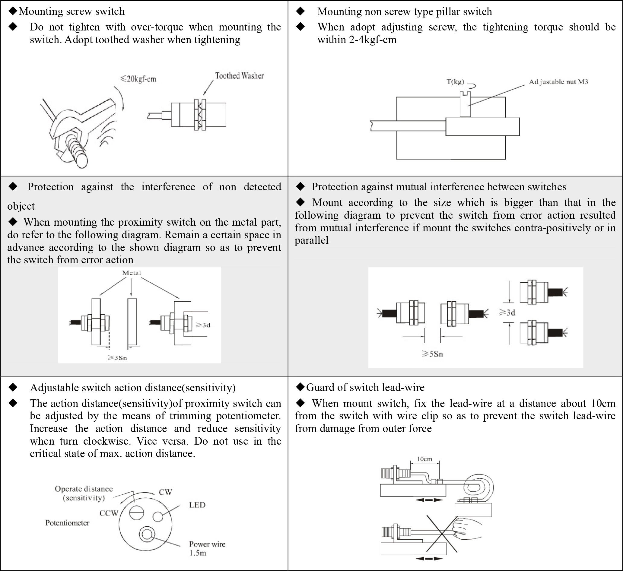
Cautions:
- DC switch should adopt insulation transformer and ensure stable voltage mains corrugation.
- IF any electric power line or dynamic line passes through the surrounding of switch lead-wire, in order to prevent the switch from damage or error action, cover the metal bushing on the switch lead-wire and ground it to the earth.
- Set the switch use distance within the rated distance to avoid the effects from temperature and voltage.
- Wiring while power-on is strictly prohibited. Connecting the wires strictly according to the wiring diagram and output return elementary diagram.
- If there are any special requirements to the switch like water proof, oil proof, acid proof, base proof, high temperature proof or with any other specifications, the users are required to give clear indication when placing an order. We can produce according to the requirements of the use.
Catalog data
-
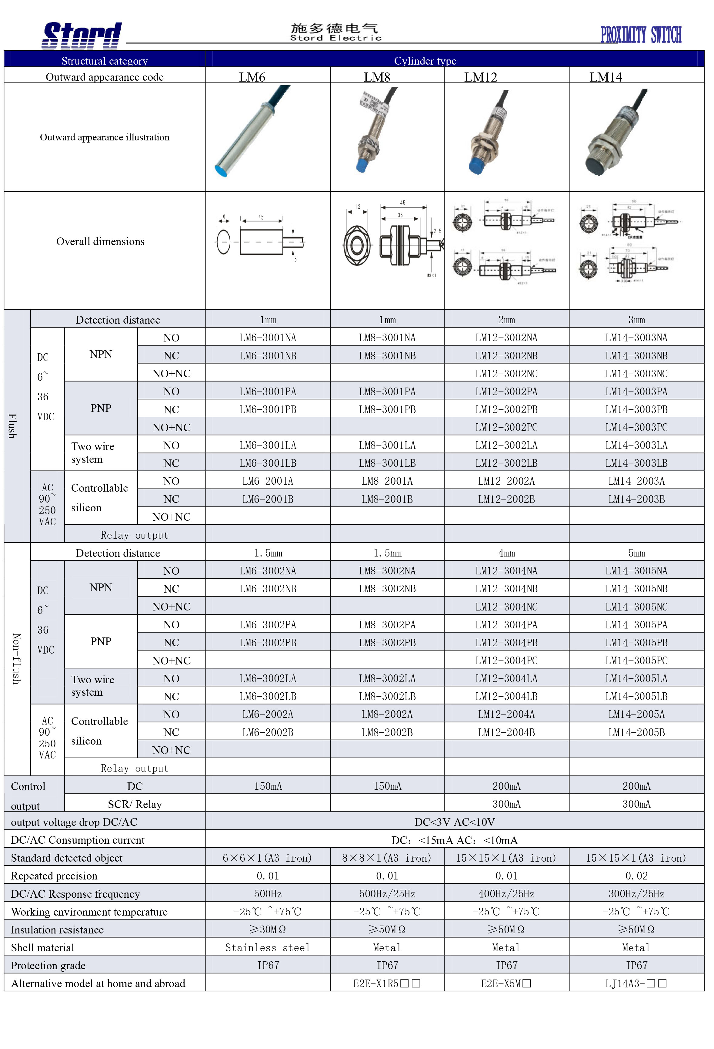
- Seria: LM6; LM8; LM12; LM14
-
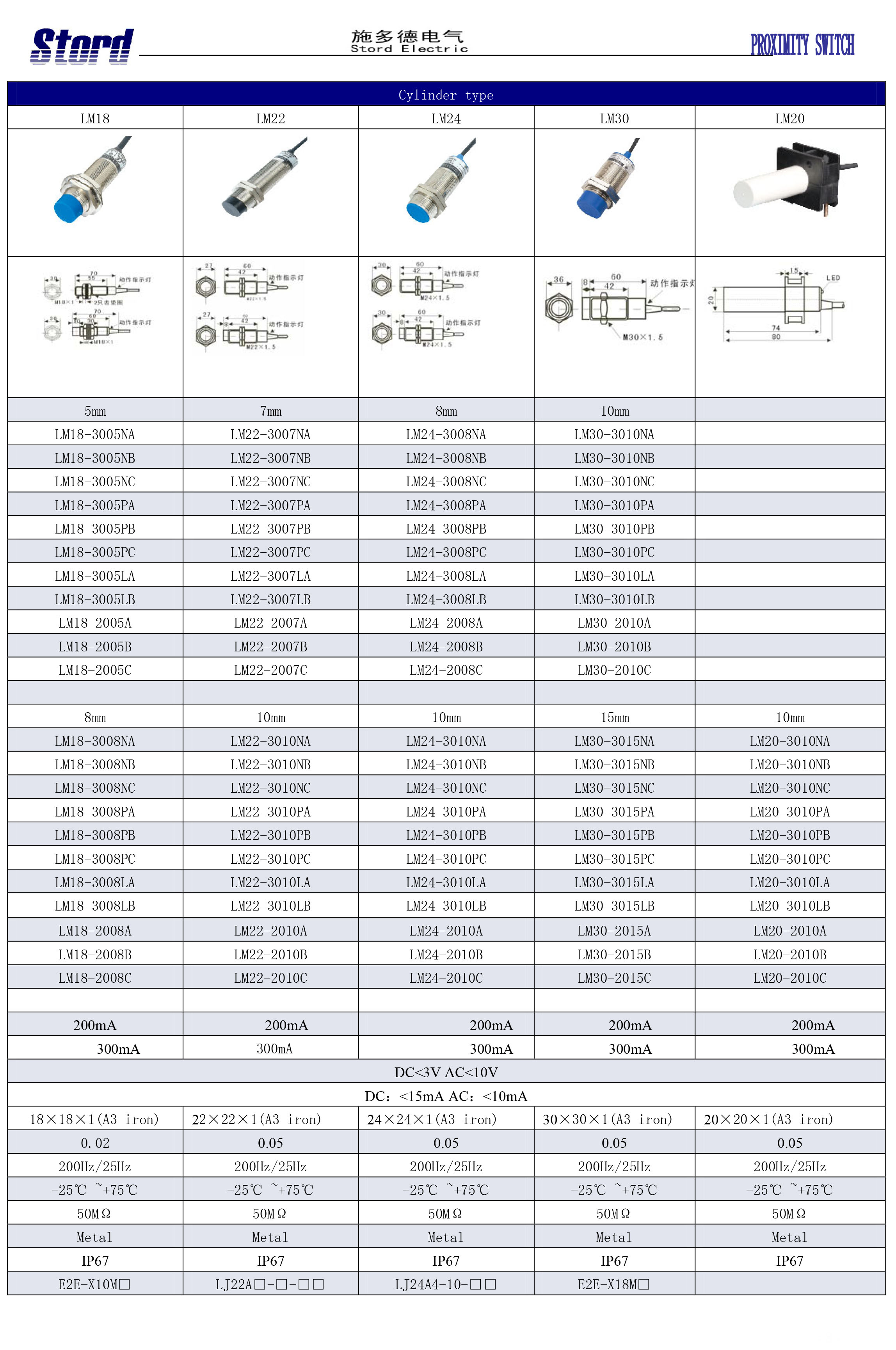
- Seria: LM18; LM22; LM24; M30; LM20
-

- Seria: LM34; LM35; LM38; LM40
-
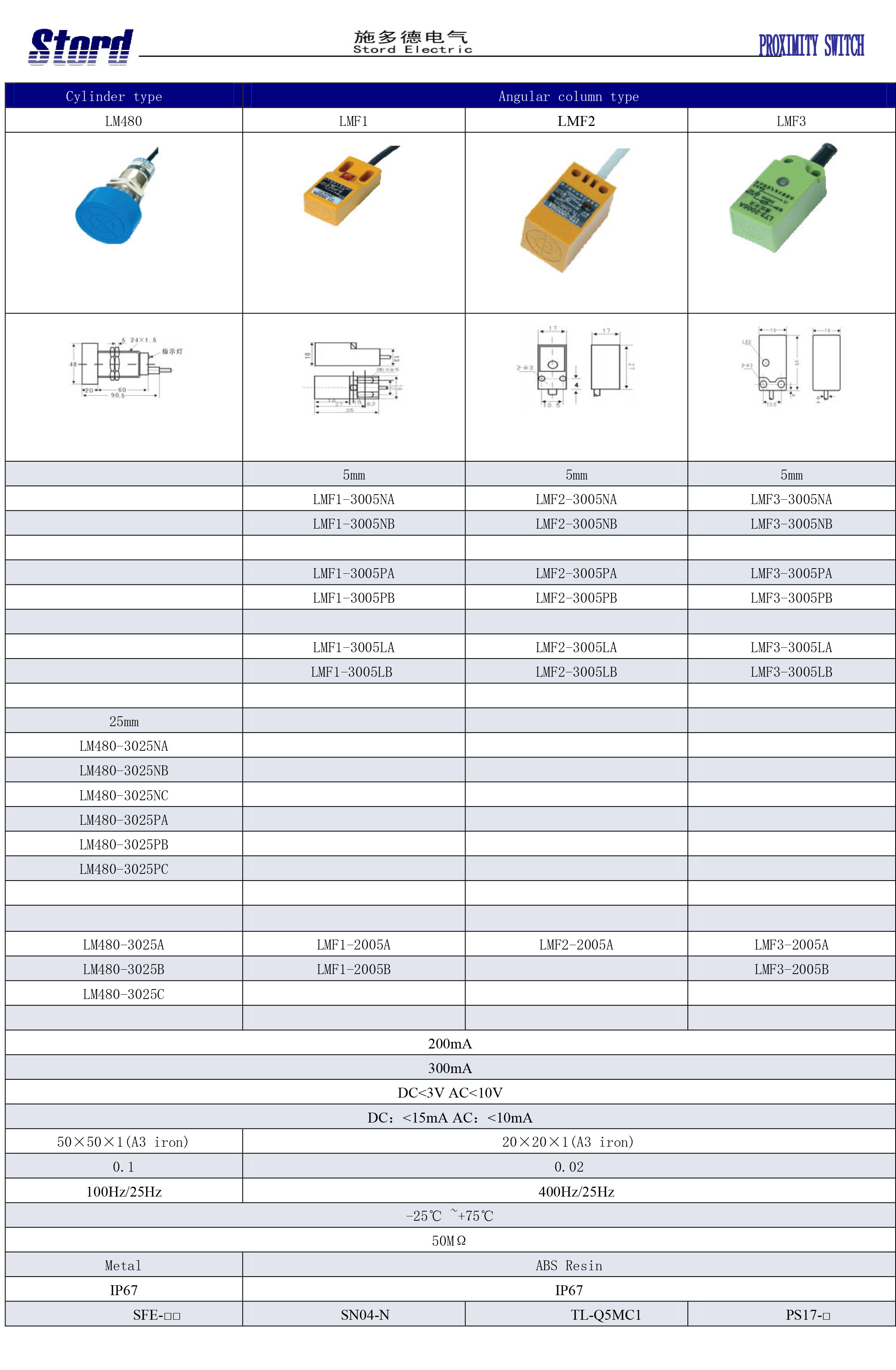
- Seria: LM480; LMF1; LMF2; LMF3
-

- Seria: LMF5; LMF6; LMF7; LMF8
-

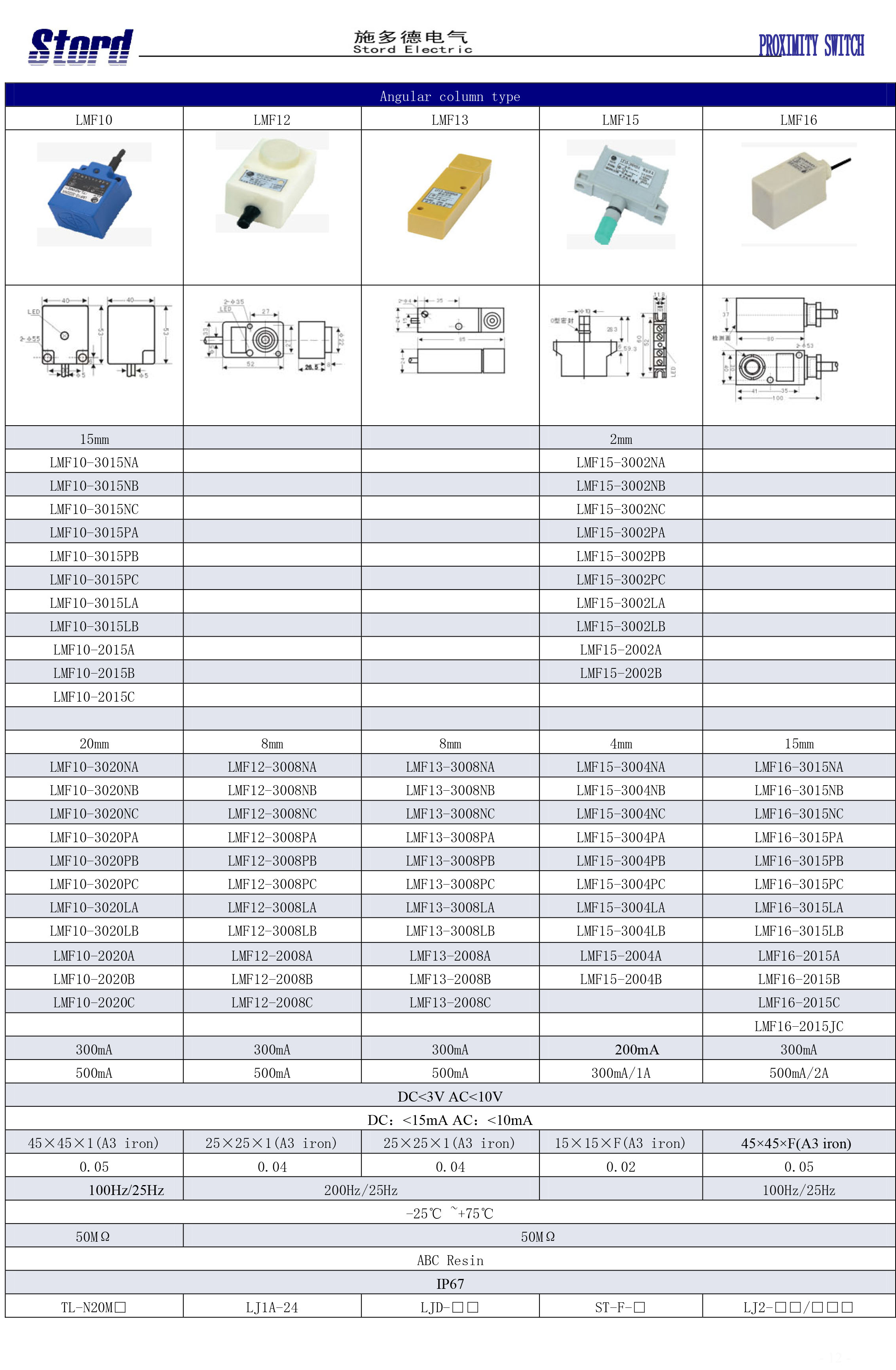
- Seria: LMF10; LMF12; LMF13; LMF15; LMF16
-
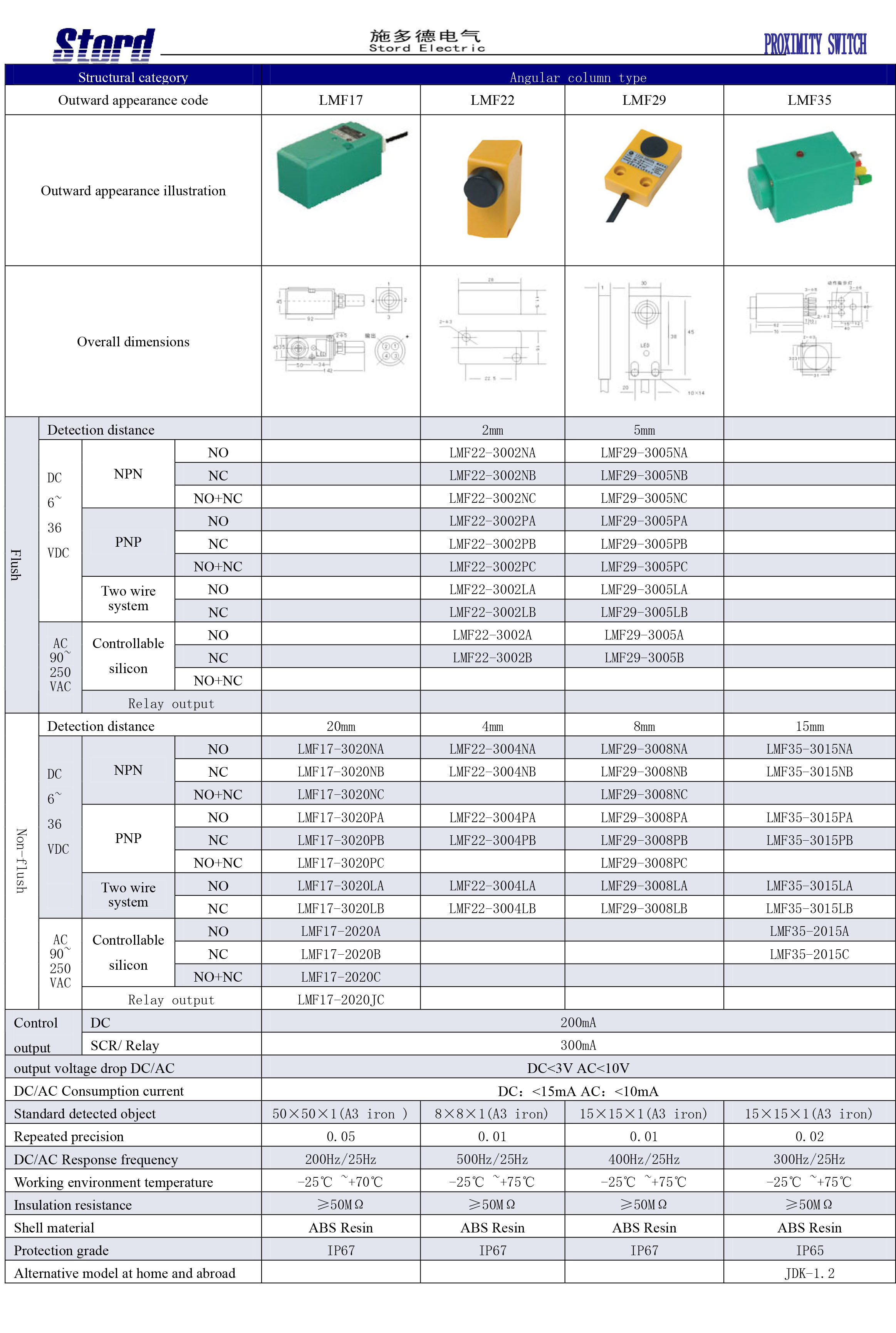
- Seria: LMF17; LMF22; LMF29; LMF35
-
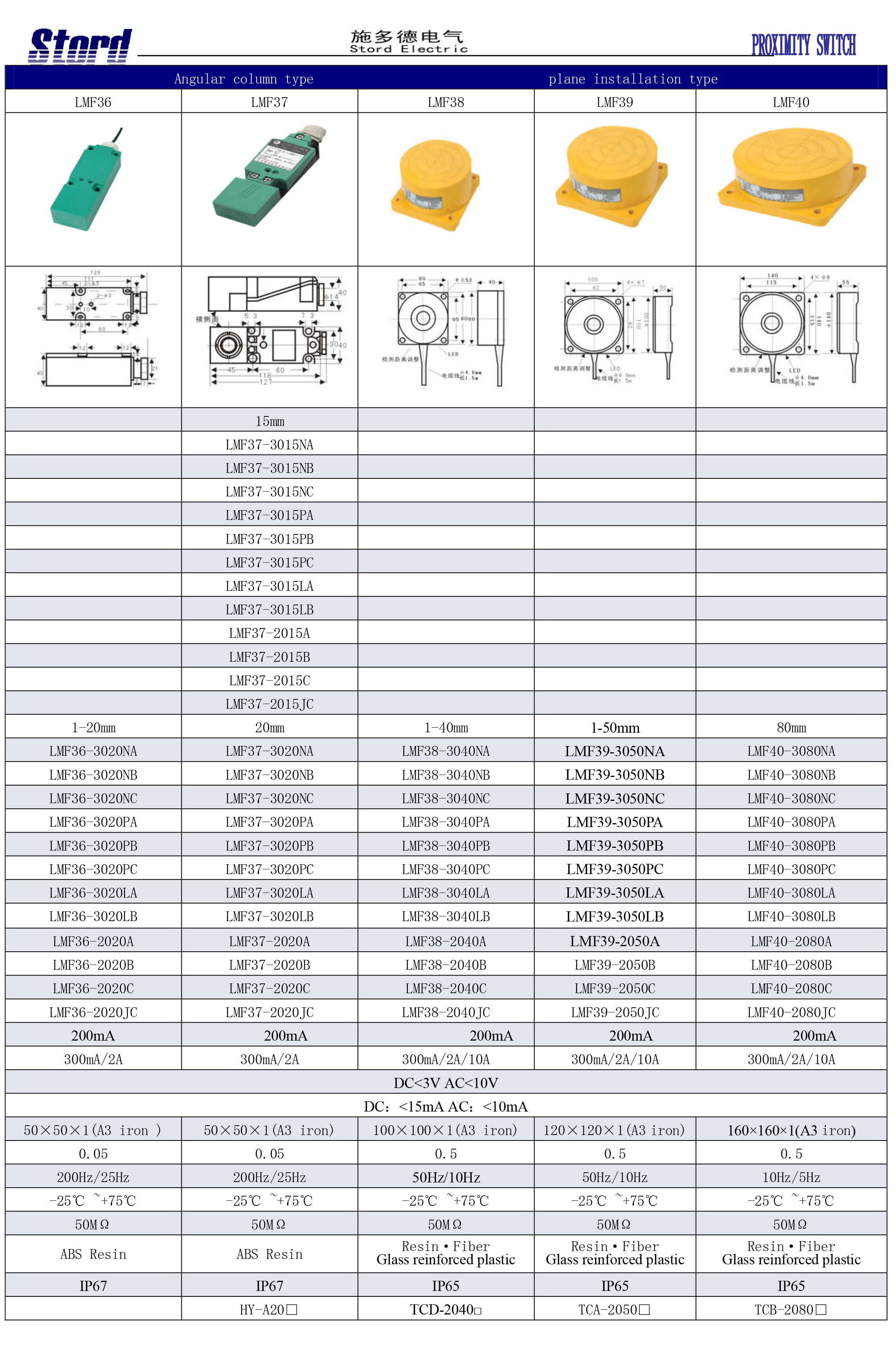
- Seria: LMF36; LMF37; LMF38; LMF39; LMF40
-

- Seria: LMF41; LMF42; LMF43; LMF50
-

- Seria: LMF55; LM36; LM42; LM48; LM55
-
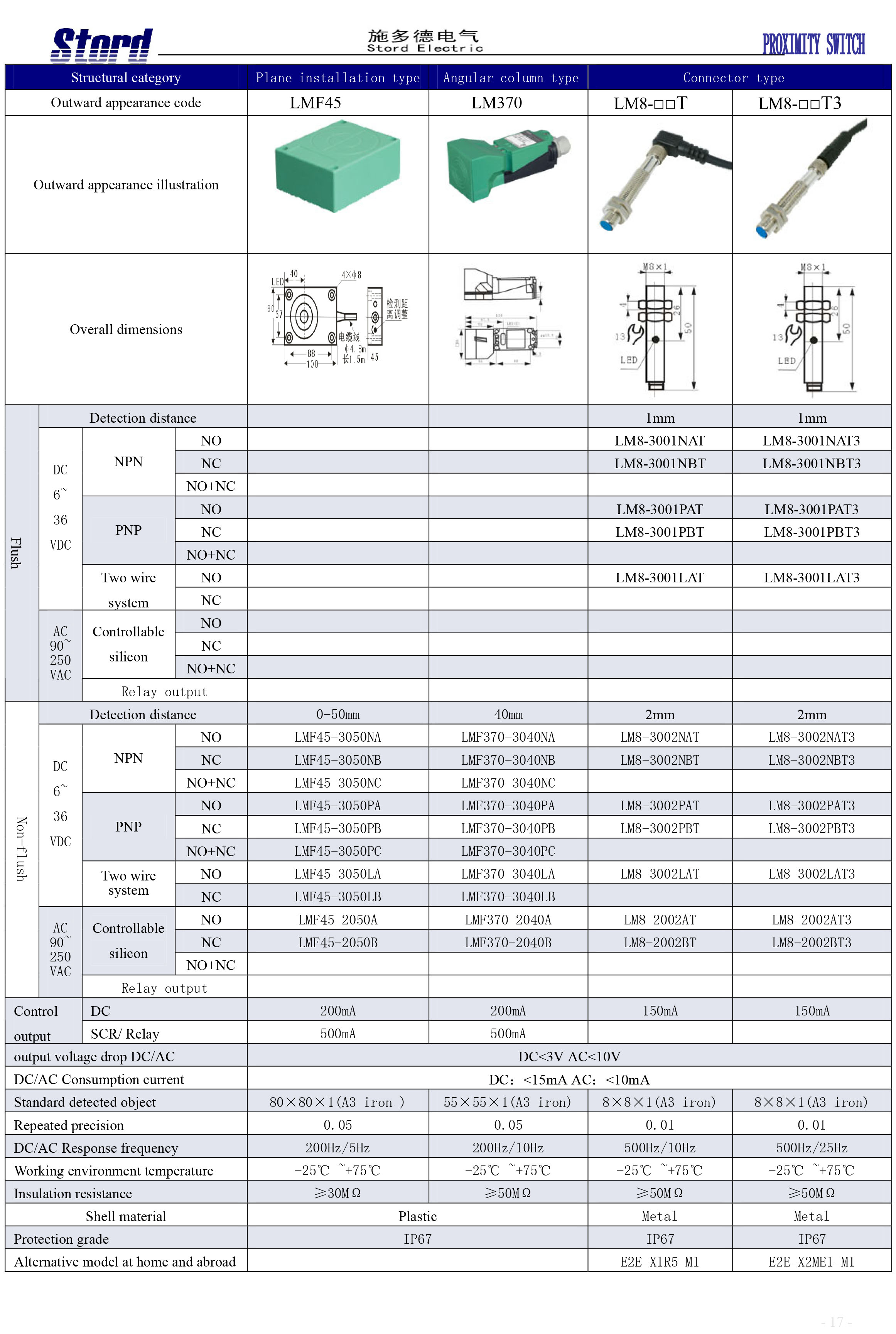
- Seria: LMF45; LM370; LM8-□□T; LM8-□□T3
-

- Seria: LM12-□T; LM12-□T3; LM18-□T; LM18-□T3; LM22-□T
-
- Seria: LM22-□T3; LM30-□T; LM30-□T3; LMF16-□T
-

- Seria: LM05; LM06; LMF4; LMF11
-
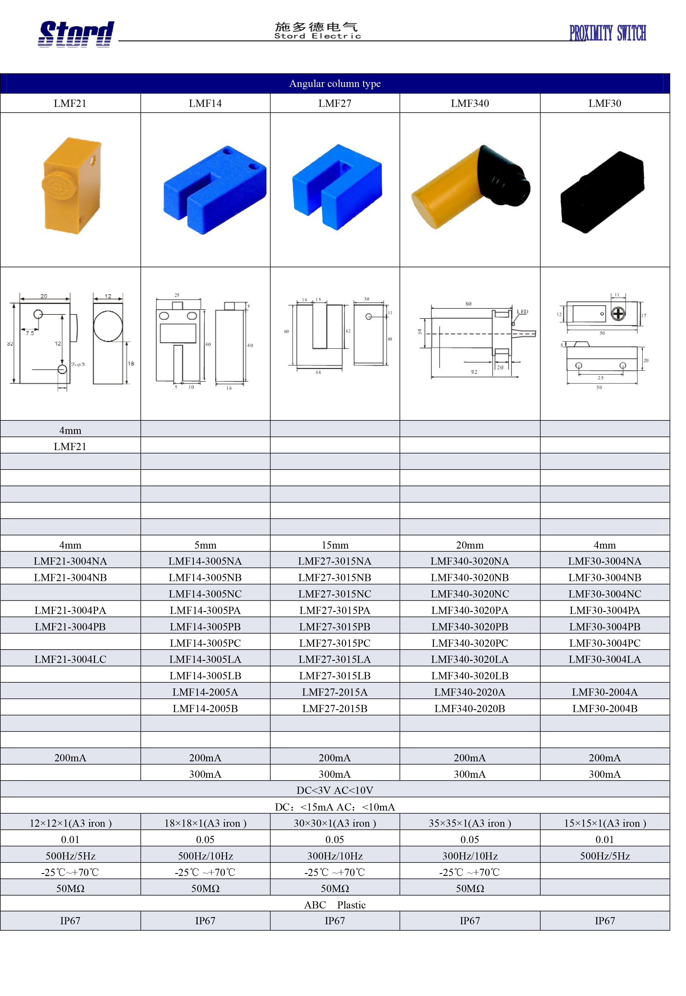
- Seria: LMF21; LMF14; LMF27; LMF340; LMF30
-
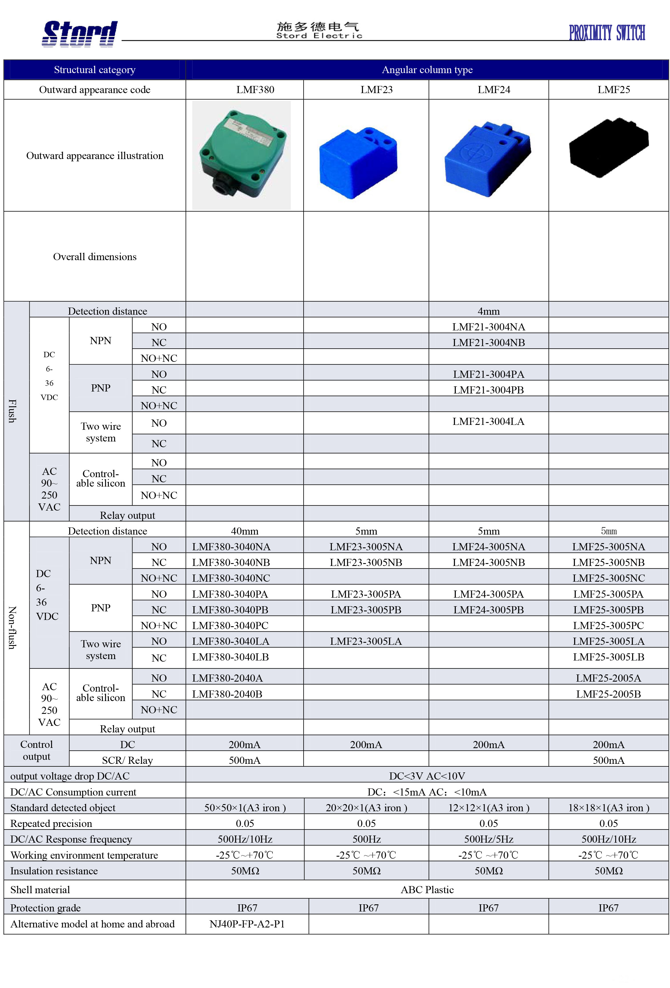
- Seria: LMF380; LMF23; LMF24; LMF25
-
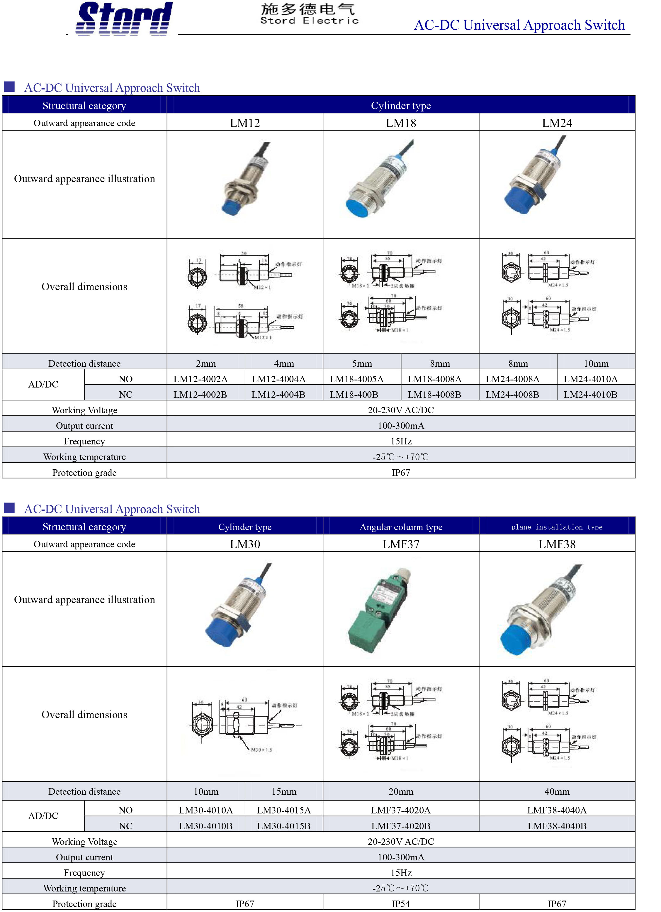
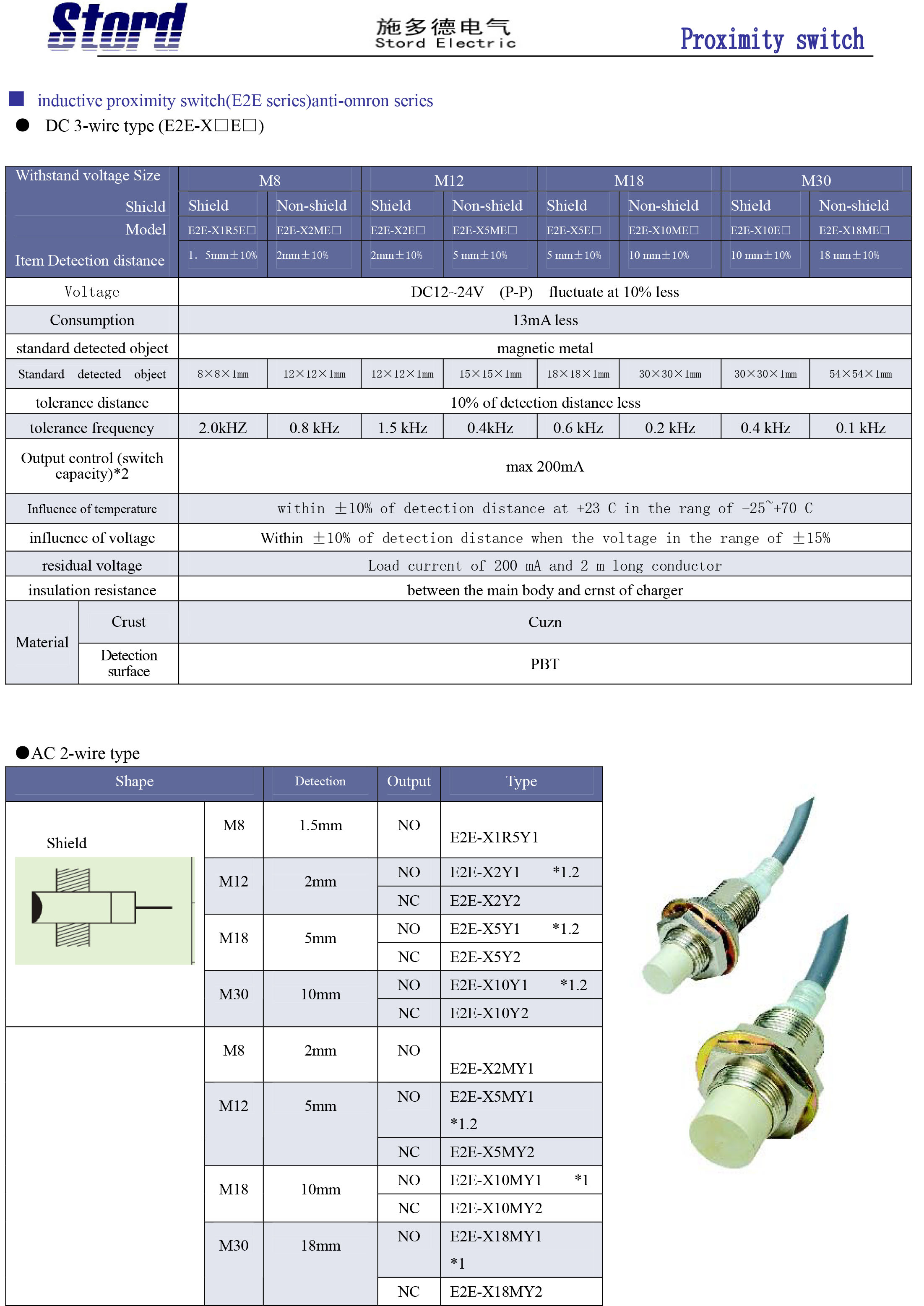
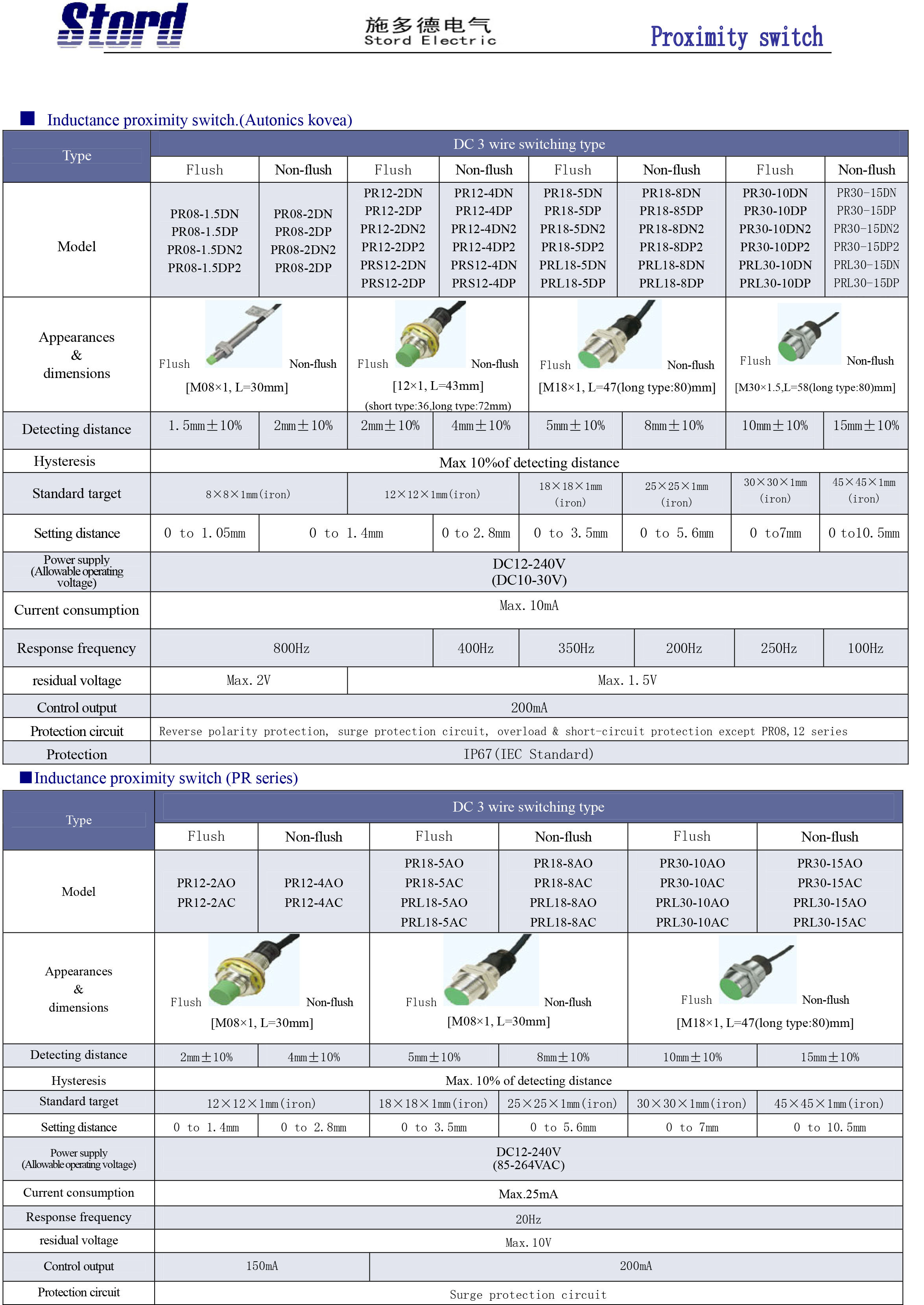
- Seria: LM12; LM18; LM24; LM30; LMF37; LMF38
-
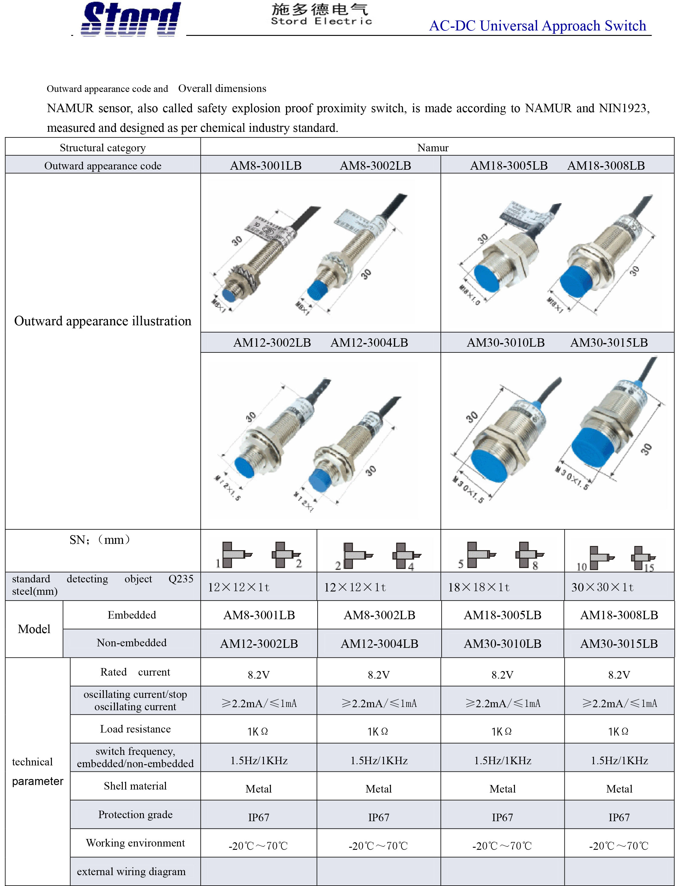
- Seria: AM8-3001LB; AM8-3002LB; AM18-3005LB; AM18-3008LB; AM12-3002LB; AM12-3004LB; AM30-3010LB; AM30-3015LB

0 komentarzy